


NEON Starting Guide
Pressure Sensor (PS)
Table of contents
The user must read the product documentation before proceeding with the information provided in this section.
The NEON Pressure Sensor is a combination of the NEON Transmitter and the NEON Pressure Sensor. The NEON Pressure Sensor must have been requested with a specification of connection and range. The NEON Transmitter must be connected to the respective sensor. The key files sent alongside the shipment confirmation provide the serial number of the transmitter and the sensor in pairs. See the following table for an example of the key files.
Transmitter ser. no. | Dev EUI | type | appEUI | appKey | Sensor art. no. |
|---|---|---|---|---|---|
RT020123AA00001 | 848BCDFFFE6137FF | DS-RT-02-01 | 848BCDFFFE613FFF | F65161475DE01C91FB68F7BAA722FFFF | 520.9-42-S-0-9-3-P-2-1 |
RT020123AA00002 | 848BCDFFFE6137FE | DS-RT-02-01 | 848BCDFFFE613FFE | F65161475DE01C91FB68F7BAA722FFFE | 520.941S093800 |
The transmitter with serial number RT020123AA00001 must be connected to the sensor with serial number 520.9-42-S-0-9-3-P-2-0, while the transmitter with serial number RT020123AA00002 must be connected to the sensor with serial number 520.941S093800. Interchanging sensors may result in completely inaccurate measurements.
NEON Transmitter
The NEON transmitter must be mounted using the pre-mounted bracket, which must be earthed. On a flat surface, you can use the mounting holes. Slots and screw holes are designed for M4 fasteners while the threaded hole uses a M5 bolt.
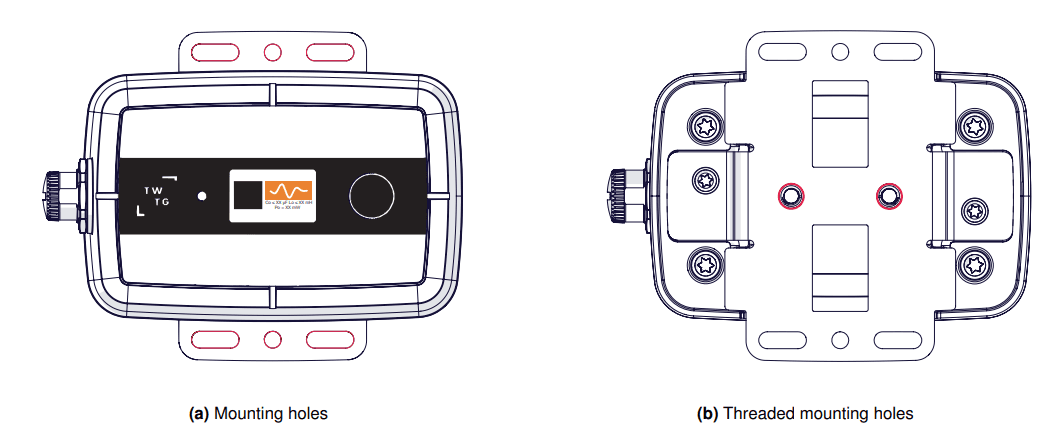
Schematic of NEON transmitter with its mounting bracket
An example of a mounted NEON transmitter using the mounting holes is presented next.
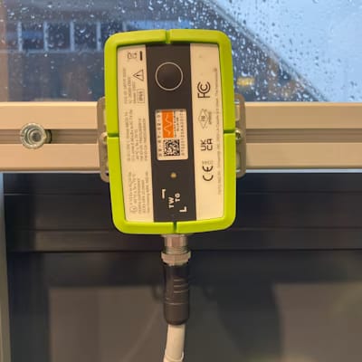
Mounted NEON transmitter
You can mount the NEON transmitter to a pole using a 14 mm wide band clamp. Please note that in this case the bracket must be earthed as well.
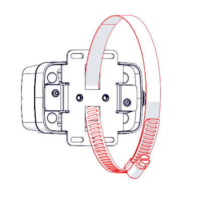
Schematic of NEON transmitter with band clamp
Pressure Sensor
When purchasing the NEON Pressure Sensor, the customer must have decided on the connection type of the sensor. Install the sensor to the connection according to the specifications and safety measures of the asset to be monitored. An example of an installed sensor is presented next.
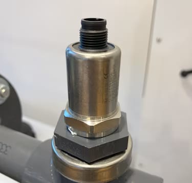
Installed pressure sensor
After finishing the physical installation of the sensor, connect the cable to the M12 plug of the sensor. The female end of the cable connects to the sensor while the male end is connected to the transmitter. Examples of each end of the cable are in the following figures.
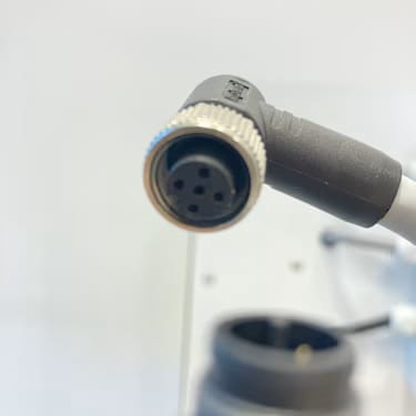
Cable's female end
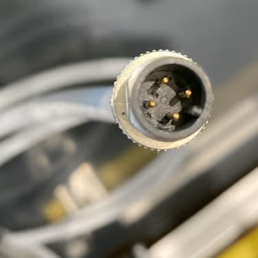
Cable's male end